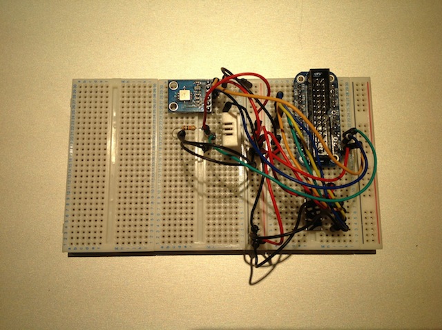
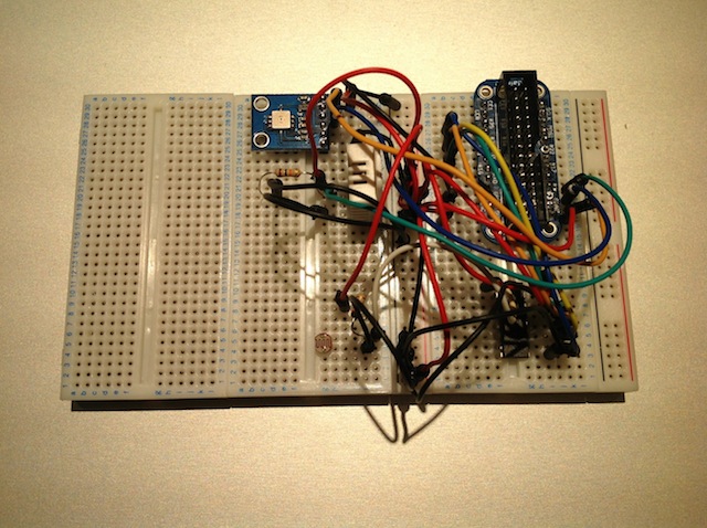
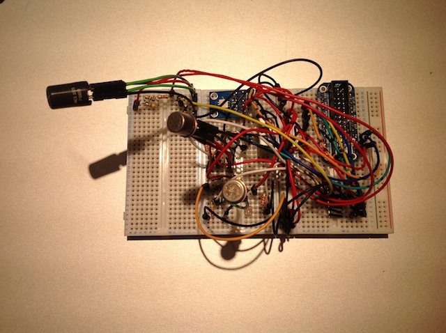
Breadboard
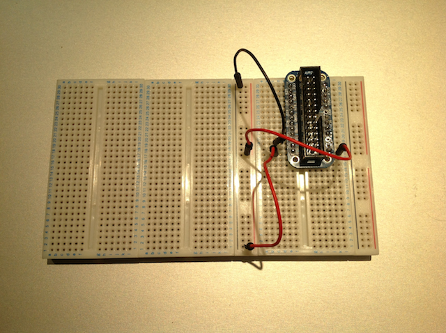
First, clip your breadboards together, with the longer sides together.
Then, if you have a Cobbler (see Step 1), push it into one of the breadboards so that its pins straddle the gap in the middle of one of the breadboards. Then proceed to connect the 5V, 3.3V, and ground outputs from the Raspberry Pi's GPIO to the rails on the side of the breadboard.
This is done because these are the most commonly used pins from the Pi, so they need to be easily accessible.
ADC
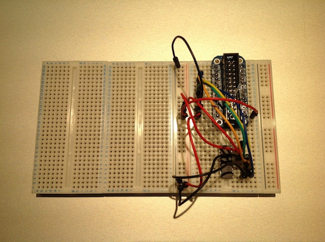
Then add your MCP3008 ADC to the breadboard in the same fashion. When looking at it from above, with the small notch at the top, the 8 pins on the right are connected to the Pi, and the 8 pins on the left are used as inputs to the ADC, normally coming from sensors you've placed onto your board. These are the connections which you need to make from the 8 right hand pins:
- Pin 1 → 3.3V
- Pin 2 → 3.3V
- Pin 3 → Ground
- Pin 4 → GPIO #18
- Pin 5 → GPIO #24
- Pin 6 → GPIO #23
- Pin 7 → GPIO #25
- Pin 8 → Ground
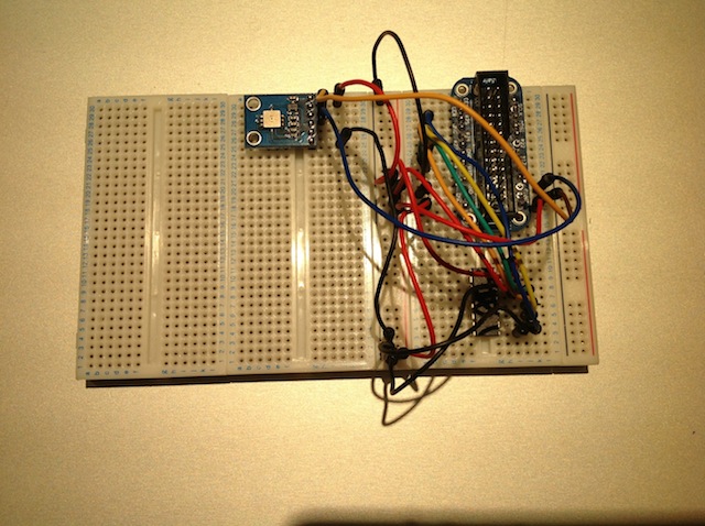
BMP085
This pressure and temperature sensor has either 6 or 7 outputs, depending on where you obtain it, however this does not impact its installation, as the pin missing from some versions is not important for our usage of the sensor. Connect the pins as follows:
- SDA → SDA0
- SCL → SCL0
- VCC → 3.3V
- GND → Ground
DHT22
While holding the sensor facing you (so you can see the grating), the pins are numbered from left to right 1, 2, 3 and 4. Connect them up like this (Pin 2 is connected to two places, that's not a typo!):
- Pin 1 → 3.3V
- Pin 2 → 3.3V via the 10KΩ resistor
- Pin 2 → GPIO #4
- Pin 4 → Ground
LDR
To connect the LDR to your breadboard, attach one end of it to ground. Connect the other end both to 3.3V via the 2.2KΩ resistor, and to the first input on the ADC (the one closest to the notch on the left).
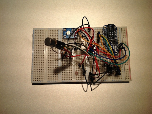
TGS 2600
If you're looking at this sensor from above, with the little bump at the top, the pins are numbered 1 to 4 working clockwise from the pin directly to the right of the bump. Connect them up like so:
- Pin 1 → 5V
- Pin 2 → 5V
- Pin 3 → Ground via the 22KΩ resistor
- Pin 3 → Input 2 of the ADC
- Pin 4 → Ground
MiCS-2710
Using the same pin numbering as for the TGS 2600, connect the pins as so:
- Pin 1 → Ground
- Pin 2 → Ground via the 10KΩ resistor
- Pin 2 → Input 3 of the ADC
- Pin 3 → 3.3V via the two small resistors (in series)
- Pin 4 → 5V
MiCS-5525
Using the same pin numbering as for the TGS 2600, connect the 4 pins like this:
- Pin 1 → Ground
- Pin 2 → Ground via the 100KΩ resistor
- Pin 2 → Input 4 of the ADC
- Pin 3 → 5V via the three small resistors (in series)
- Pin 4 → 5V
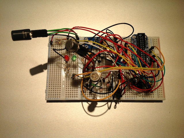
LEDs
Connect the shorter leg of both resistors to ground via a resistor each. Then connect the longer leg of the red LED to GPIO #21, and the longer leg of the green LED to GPIO #22.
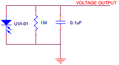
UVI-01 UV Sensor
Insert the UV sensor, the capacitor and the 1MΩ resistor into the breadboard so that they are connected in parallel, and then connect the whole thing to ground on one side and to pin 3 (the non-inverting input) of the op-amp on the other side. Here's a small circuit diagram:
Then connect the remaining pins on the op-amp follows:
- Pin 2 → Ground via the 10K resistor
- Pin 2 → Pin 6 via the 4.7MΩ resistor
- Pin 4 → Ground
- Pin 6 → Pin 4 of the ADC
- Pin 7 → 5V